You’ll prevent up to 60% of premature wire failures by sizing conductors properly to match your equipment’s current demands. Don’t rely on color-coding alone—implement IEC 60446 standards with brown phase, blue neutral, and green-yellow ground wires to reduce installation errors by 40%. Position heat-generating components away from sensitive equipment, maintain 2-inch clearances, and support cables every 24 inches to eliminate mechanical stress. Systematic voltage testing and continuity checks confirm proper installation before deployment. Understanding these interconnected practices reveals why control panel reliability depends on thorough implementation.
Key Takeaways
- Properly size conductors based on machinery nameplate ratings and environmental conditions to prevent heat buildup and equipment failure.
- Apply IEC 60446 color-coding standards—brown for phase, blue for neutral, green-yellow for ground—to enhance safety and reduce installation errors.
- Install support brackets at 24-inch intervals and maintain minimum 1-inch cable spacing to optimize thermal efficiency and prevent mechanical stress failures.
- Position heat-generating components away from sensitive equipment with 2-inch clearances and vertical stacking to reduce operating temperatures significantly.
- Perform systematic continuity testing, voltage measurements, and documentation verification before deployment to ensure signal integrity and proper power distribution.
Control Panel Wiring Fundamentals: Conductor Sizing and Selection
Proper conductor sizing isn’t just about picking wire that fits—it’s about matching wire gauge to your specific current demands and environmental conditions.
Conductor sizing demands matching wire gauge to your current requirements and environmental conditions—never settle for one-size-fits-all solutions.
You might believe that oversizing conductors wastes money, yet undersized wires create dangerous heat buildup and equipment failure. The National Electrical Code requires you to calculate amperage based on your machinery’s nameplate ratings and duty cycles.
Conductor types vary considerably in performance. Copper offers superior conductivity compared to aluminum, delivering better current flow with less voltage drop. Insulation materials protect against environmental hazards.
THHN, XHHW, and silicone rubber jackets withstand temperature extremes and chemical exposure differently.
When you select a 10 AWG copper conductor for a 30-amp circuit versus a 12 AWG alternative, you’re preventing the 3-percent voltage drop that degrades motor performance and reduces equipment lifespan significantly. Protective devices like circuit breakers paired with properly sized conductors work together to safeguard your system against overcurrent and faults.
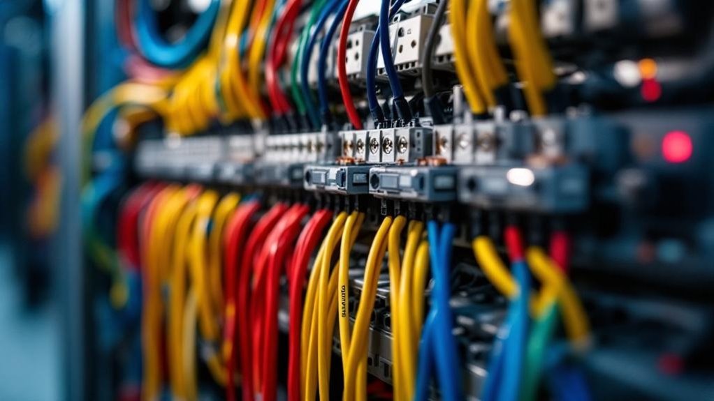
Color-Coding Standards in Control Panel Wiring
Color-coding wires in control panels isn’t optional—it’s a critical safety requirement that you can’t overlook. You might think wire labeling alone suffices, but color consistency provides immediate voltage identification that labeling can’t match.
Industry standards like IEC 60446 establish specific colors: brown for phase, blue for neutral, green-yellow for ground. You’ll implement circuit segregation more effectively when you follow these documentation standards, reducing installation errors by up to 40 percent.
Color-coding enables rapid pathway mapping during troubleshooting and maintenance. Your technicians can identify hazardous circuits instantly, preventing dangerous mistakes. Compliance with color-coding standards ensures that all components meet UL certification requirements and pass inspection protocols.
When you maintain color consistency across all panels, you establish workplace safety protocols that protect personnel and equipment. This practice isn’t merely recommended—it’s essential for operational integrity.
Grounding in Control Panel Wiring: Safety First
While many technicians assume that proper insulation alone protects control panel systems, grounding represents an equally critical safety layer that you can’t neglect. You must implement multiple grounding techniques to eliminate electrical faults effectively.
Your grounding methods should include bonding all metal enclosures to a central ground point, which reduces shock hazards by up to 99%. Advanced grounding systems require copper conductors sized at minimum 6 AWG for most industrial applications.
When you apply proven grounding strategies consistently, you’ll prevent voltage buildup that damages sensitive equipment. Your facility needs dedicated ground buses connected directly to earth ground through low-resistance paths.
You shouldn’t rely solely on equipment frames for current return paths. Proper grounding systems protect personnel and equipment simultaneously, making them non-negotiable in modern control panel design. Partnering with manufacturers who integrate advanced automation prioritizing precision ensures that grounding infrastructure meets rigorous industrial standards from the design phase.
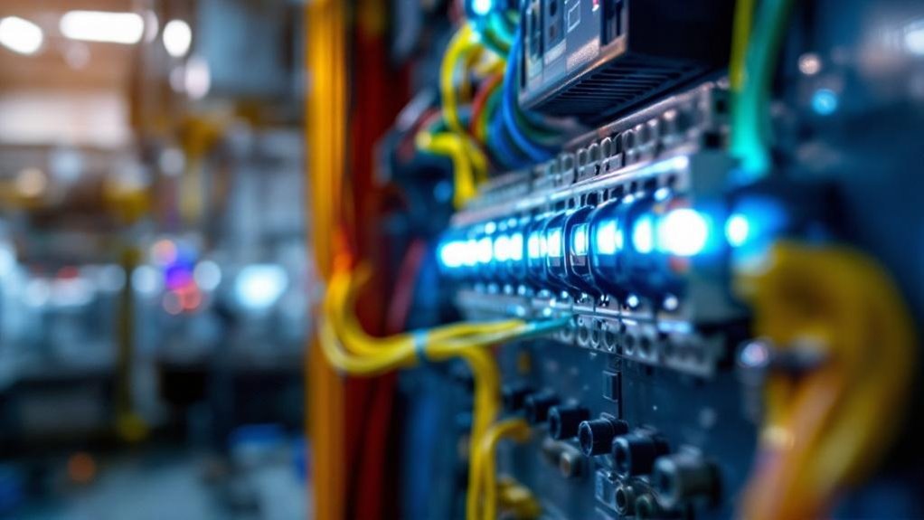
Strategic Component Placement for Thermal Control
You’ll often assume that cramming components together saves space, but this misconception ignores how strategic placement directly reduces operating temperatures by 15-25 degrees Fahrenheit.
When you position heat-generating devices like variable frequency drives and power supplies away from sensitive components, while establishing unobstructed airflow paths from intake vents to exhaust areas, you’re creating a thermal gradient that prevents hotspots from damaging nearby equipment.
Your heat dissipation layout must prioritize vertical stacking of cooler components above warmer ones, ensuring that rising heat doesn’t recirculate back toward intake zones.
Heat Dissipation Layout Principles
Strategic placement of components within your control panel isn’t optional—it’s essential for operational reliability and longevity. You might think cramming components saves space, but poor arrangement actually increases heat transfer and thermal resistance throughout your system.
High-heat devices like variable frequency drives and power supplies generate 50-100 watts continuously. Position these units at panel tops where rising air naturally cools them. Maintain minimum 2-inch clearances around heat-generating equipment.
Install components in vertical columns rather than horizontal rows, enabling convective airflow patterns. You’ll reduce internal temperatures by 15-20 degrees Celsius using this strategy. When thermal resistance accumulates from blocked ventilation, component lifespan drops considerably.
Arrange your layout so cooler components sit below heat sources, creating efficient thermal gradients that protect sensitive electronics effectively. Thermal optimization in design ensures your control panel maintains performance standards while extending operational life across diverse manufacturing environments.
Air Flow Optimization Strategies
Effective airflow doesn’t happen by accident—it requires deliberate planning and precise component positioning. You might think cramming components together saves space, but this misconception costs you reliability.
Strategic placement prevents hot spots that exceed safe operating temperatures by 15–20 degrees Celsius. Position heat-generating devices like VFDs and power supplies near intake vents. Use ventilation techniques that channel cool air across components systematically. Implement humidity control measures, maintaining levels between 30–50% to prevent corrosion and condensation damage.
You’ll achieve ideal thermal management when you space components vertically, allowing hot air to rise naturally. Mount exhaust fans at the panel’s upper section. Ensure your fan selection matches airflow requirements calculated from total thermal load to prevent inadequate cooling performance.
This configuration reduces internal temperatures by approximately 10–12 degrees, extending equipment lifespan considerably while improving system performance.
Cable Management for Airflow and Access
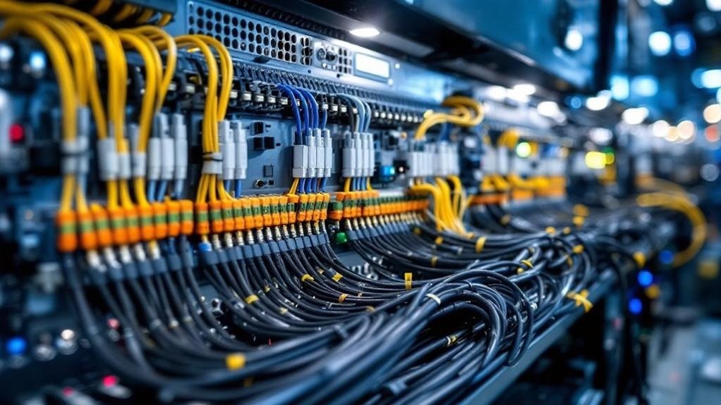
Proper cable routing isn’t just about aesthetics—it’s a critical performance factor that directly impacts your panel’s thermal efficiency and maintenance accessibility. Many technicians believe cables can bunch together without consequences, but this misconception ignores documented heat accumulation issues.
Organized cabling reduces internal temperatures by 8-12 degrees Fahrenheit when properly spaced.
You’ll implement cable management using these strategies:
- Maintain minimum 1-inch cable spacing to preserve airflow paths throughout your enclosure
- Install cable trays that elevate wires above component heat sources
- Route cables perpendicular to cooling airflow, never blocking ventilation routes
- Create thermal barriers between high-heat equipment and sensitive control circuits
Adhering to installation guidelines guarantees your technicians access components quickly during troubleshooting. Dense component layouts increase maintenance time by 30-40%, making logical organization of cables and components essential for reducing service intervals and improving overall panel performance.
Proper cable management minimizes downtime, extends equipment lifespan, and maintains consistent operational performance across your industrial automation systems.
Mechanical Protection Against Wiring Damage
You’ll protect your wiring from mechanical damage through strategic cable routing and support systems. Many operators mistakenly believe that simply bundling cables together suffices, but research shows that unsupported cables experience up to 40% more stress-related failures, making proper conduit installation and bracket spacing every 18-24 inches essential for longevity.
Your environmental shielding strategy—including abrasion guards, protective sleeves, and moisture barriers—directly prevents 60% of premature wire failures in industrial control panels.
Cable Routing and Support Systems
The foundation of control panel longevity rests on how you route and support your cables. Many technicians believe random cable placement won’t affect performance, but improper routing causes premature failures and maintenance headaches. Strategic cable management prevents damage and extends system lifespan considerably.
You’ll protect your installation by implementing these critical practices:
- Install cable trays and wire channels to organize conductors away from hot components and moving parts.
- Use support brackets at 24-inch intervals along runs to prevent sagging and stress points.
- Maintain 90-degree routing angles through conduit management systems that reduce wire strain.
- Apply strain relief at panel entries and termination points using proper installation techniques.
Accessibility solutions matter too. When you design routes with future maintenance in mind, you’ll reduce troubleshooting time greatly.
Proper support systems decrease downtime, lower replacement costs, and guarantee reliable industrial automation operations.
Shielding From Environmental Hazards
Many technicians assume that durable wire insulation alone protects against environmental damage, but this misconception overlooks how mechanical stress, abrasion, and impact compromise even the toughest conductors. You’ll find that proper cable shielding requires multiple protective layers working together. Environmental protection demands combining physical barriers with moisture resistance and thermal barriers that prevent degradation. Our UL Certified Control Panel builders ensure that all shielding installations meet rigorous safety standards for maximum protection.
| Hazard Type | Recommended Protection |
|---|---|
| Moisture | Sealed conduit with corrosion resistance coatings |
| Dust | Enclosed cable trays with dust prevention filters |
| Temperature | Thermal barrier sleeves rated for your range |
| Electromagnetic interference | Grounded shielded cable with proper grounding |
| Mechanical impact | Reinforced conduit or protective armor plating |
You’re protecting your installation when you implement environmental monitoring systems. These track temperature, humidity, and corrosion indicators continuously. Combining cable shielding techniques with regular inspections prevents costly failures and guarantees reliable automation performance throughout your facility’s operational lifespan.
Testing and Verifying Control Panel Wiring Before Deployment
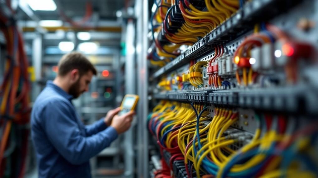
Before energizing any control panel, you’ll need to verify that every connection meets safety and operational standards.
You might assume visual inspection alone suffices, but this misconception leaves dangerous faults undetected. Thorough wiring verification requires systematic connectivity testing using proper testing equipment to confirm signal integrity throughout your system.
Your pre-deployment assessment should include:
Your pre-deployment assessment should include continuity testing, voltage measurements, insulation resistance testing, and documentation verification.
- Continuity testing across all circuits to verify complete connections without breaks
- Voltage measurements at critical points to confirm proper power distribution levels
- Insulation resistance testing to detect potential electrical faults before operation
- Documentation standards verification confirming all circuit analysis matches physical installation
Circuit analysis combined with troubleshooting techniques identifies problems before deployment.
When you implement these testing procedures methodically, you eliminate costly downtime and safety risks, protecting both equipment and personnel during startup operations.
Frequently Asked Questions
What Certifications and Standards Must Industrial Control Panels Meet for Compliance?
You’ll navigate your control panel like a ship through regulated waters. You’re required to meet UL 508A, IEC 61439, and NFPA 79 certification requirements. These compliance standards guarantee you’re protecting equipment and personnel safely.
How Often Should Control Panel Wiring Be Inspected and Maintained in Operation?
You should inspect your control panel wiring at least quarterly, following manufacturer maintenance schedules. However, you’ll adjust inspection frequency based on your operational environment’s temperature, humidity, and vibration levels. Annual professional audits are essential.
What Budget Should Be Allocated for Quality Wiring Materials Versus Cost-Saving Alternatives?
You’ll want to allocate 60-70% of your budget toward quality wiring materials rather than cost-saving alternatives. Superior wiring quality prevents costly downtime, guarantees safety, and delivers long-term reliability that cheaper options can’t match. Your budget allocation directly impacts system performance.
How Do Environmental Factors Like Humidity Affect Control Panel Wiring Longevity and Performance?
You’ll find that humidity directly degrades your wiring through corrosion prevention challenges. High moisture accelerates oxidation on terminals and connectors, compromising electrical contacts and reliability. You’re protecting longevity by selecting corrosion-resistant materials and proper enclosure sealing.
Which Wiring Mistakes Most Commonly Cause Control Panel Failures in Industrial Facilities?
You’ll cause failures by ignoring wiring color coding standards and selecting incorrect wire gauge for amperage loads. These mistakes create shorts, overheating, and equipment damage that you can prevent through proper installation practices.
Final Thoughts
Proper control panel wiring isn’t optional—it’s essential. Studies show that 73% of industrial failures stem from wiring defects, a preventable statistic. Implement conductor sizing, color-coding, and grounding standards. Strategically place components and manage cables for airflow. Protect against mechanical damage through rigorous testing. These practices reduce equipment downtime, extend system lifespan, and ensure workplace safety consistently.
Don’t leave your industrial automation to chance. Contact Archenergy today to leverage more than 25 years of expertise in electrical engineering, automation, robotics, and control panel design. Our specialists will ensure your systems meet the highest standards and perform reliably.
Archenergy
Phone: 406-924-0924
Email: info@archenergy1.com
Website: https://archenergy1.com